Multisim is a Windows-based simulation tool from National Instruments (NI) for board-level analog/digital board design. It contains the graphical input of the circuit schematic, the circuit hardware description language input method, and has a wealth of simulation analysis capabilities.
Engineers can use Multisim to interactively build schematics and simulate circuits. Multisim refines the complexities of SPICE simulation so that engineers can quickly capture, simulate, and analyze new designs without having to understand the in-depth SPICE technology, making it more suitable for electronics education. With Multisim and virtual instrumentation technology, PCB design engineers and electronics educators can complete a complete integrated design flow from theory to schematic capture and simulation to prototyping and testing.

Where is the ammeter in the Multisim circuit simulation software? Many people can't find where the Multisim circuit table is. The following small series will show you the different people who need it.
The problem is as follows:
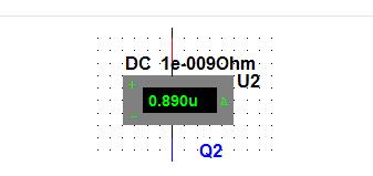
Where is the ammeter in the Multisim circuit simulation software?
In the Multisim circuit simulation software, the ammeter is in the position shown in the figure. I believe you will understand a lot after reading the picture.
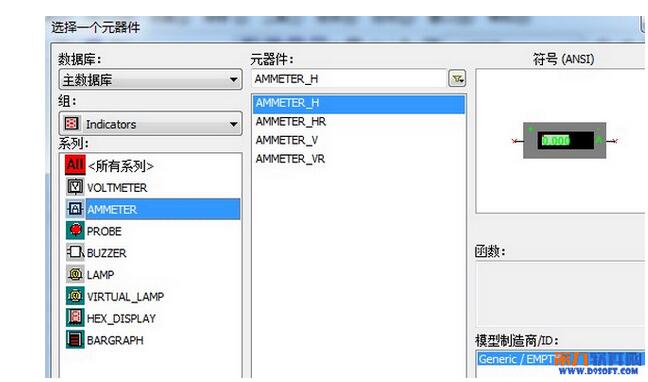
If you can't find the ammeter again next time, you can look at this picture~
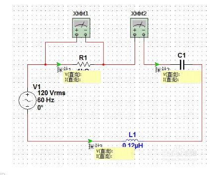
Multisim simulation ammeter usage1. In the circuit simulation process, we often observe the voltage value of a certain node and the current value of a certain branch. Generally, we can connect the voltmeter and the series current meter in parallel at the corresponding position. This method is more common but there are two main problems, one It is necessary to place the multimeter and then connect it. When it is observed, it needs to open the universal surface plate. It is not only troublesome to operate but also complicated and dense in the circuit diagram, which will cause interference to our observation. Second, placing the multimeter will have a slight impact on the circuit; in fact, in multisim The detection and display functions of voltage and current can be easily realized by using a probe;
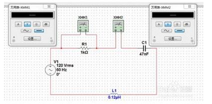
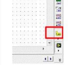
2, the so-called probe, as the name suggests, this is only a virtual tool in the circuit simulation analysis, in reality does not exist. The probe is below the instrument bar, as shown below:
3. Select the probe, then click on the probe tool to be placed on the branch node to be observed. After placing the probe, the yellow data display box will be displayed. By default, from top to bottom: instantaneous voltage, peak Peak voltage, RMS voltage, DC voltage, instantaneous current, peak-to-peak current, RMS voltage flow, DC current, frequency;
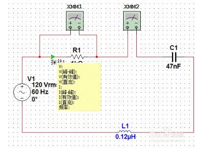
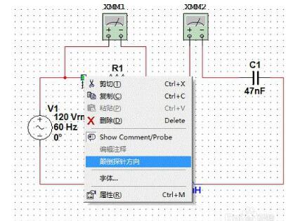
4. The arrow indicates the direction of the branch current. If the actual direction is opposite, the current correlation value is negative. If you want to reverse the direction, right click on the probe to select the reverse direction. At the same time, right-click the property menu to set the display details and font. As shown in the figure, in the parameter tab, you can set whether the relevant data item is displayed, as shown in the figure;
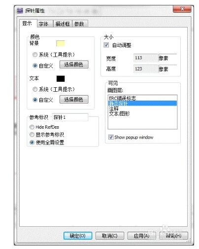
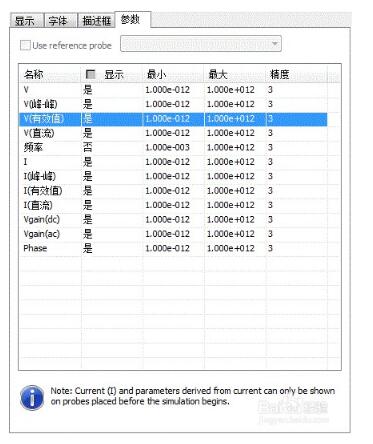
5, under normal circumstances, we often only care about a part of the data, such as only observe the DC voltage and DC current, then if you want to close the other data display after using the probe of the instrument toolbar, you need to adjust one by one, here are One trick is to use the copy-and-paste function to place the same settings as the copied device. This technique is also suitable for other devices;
Coaxial Speaker,5 Inch Coaxial Speaker,Coaxial Speaker For Fullrange Box,Neodymium Coaxial Speaker
Guangzhou BMY Electronic Limited company , https://www.bmy-speakers.com